


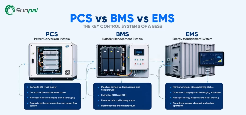
Battery energy storage systems are no longer optional add-ons in modern solar projects. Whether you are designing a commercial rooftop hybrid system, a large-scale solar-plus-storage plant, or a utility grid-support asset, the performance, safety, and bankability of the entire installation depend on three critical control layers working in perfect coordination: the Battery Management System (BMS), the Power Conversion System (PCS), and the Energy Management System (EMS).
Many solar developers, EPCs, and asset owners still treat these three acronyms as roughly interchangeable. That misconception regularly leads to underspecified systems, unexpected derating, safety incidents, or revenue shortfalls. This article clarifies exactly what each system does, how they interact inside a complete BESS architecture, and why their seamless integration determines the long-term success of any solar energy storage project.
We will examine the systems through the practical five-layer hierarchy used across the industry—Plant → Container → Rack → Module → Cell—and show how supporting components such as liquid cooling, fire suppression, busbars, MV switchgear, and transformers fit into the picture.
Why Solar Professionals Keep Confusing PCS, BMS, and EMS
In the fast-growing solar energy storage market, project teams often focus heavily on battery capacity (MWh) and inverter rating (MW). Yet the real differentiator between a high-performing system and one that under-delivers is how intelligently the BMS, PCS, and EMS talk to one another.
Simply put:
- The BMS answers: “Is the battery safe and healthy right now?”
- The PCS answers: “Can we convert and deliver the required power?”
- The EMS answers: “When and why should we charge or discharge?”
These are three distinct jobs. When they are poorly coordinated, even the best lithium-iron-phosphate cells and the highest-efficiency solar array will disappoint.
The Five-Layer BESS Architecture Every Solar Project Needs to Understand
A modern battery energy storage system is not a single black box. It is a hierarchical structure that scales from individual cells all the way to the grid interconnection point.
Plant level – Multiple BESS containers, medium-voltage transformers, switchgear, SCADA, and the overall Energy Management System or Power Plant Controller.
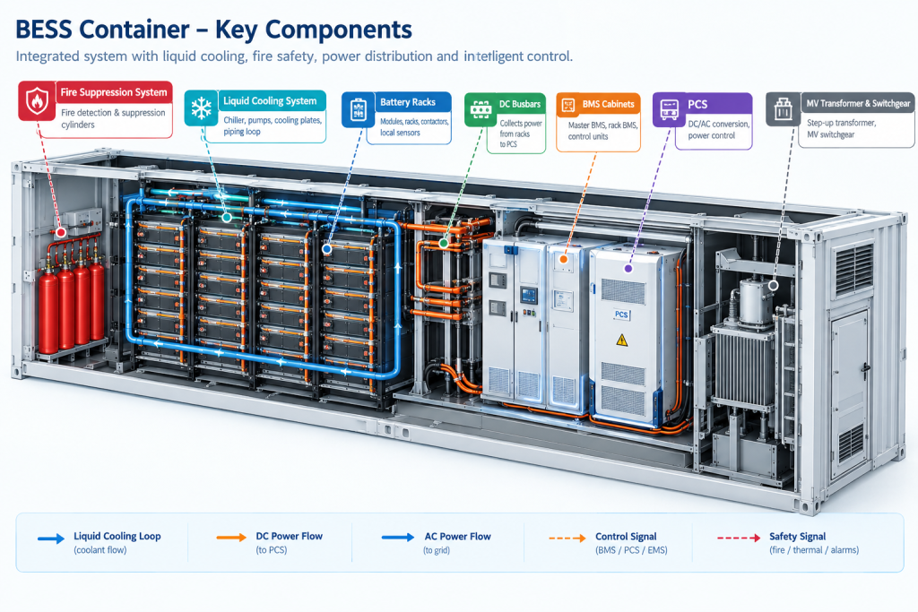
Container level – The physical enclosure that houses battery racks, the master BMS, PCS units (or string PCS), liquid-cooling or HVAC systems, fire suppression, DC busbars, and thermal propagation barriers.
Rack level – Vertical assemblies of modules with their own rack BMS, contactors, and local monitoring.
Module level – Groups of cells with module-level sensing and balancing boards.
Cell level – The fundamental electrochemical storage units.
Energy flows primarily along the power path: cells → modules → racks → DC bus → PCS → transformer → grid.
Control information flows in the opposite direction and also laterally: EMS setpoints cascade downward, while BMS limits and status data flow upward.
Understanding this architecture is the foundation of successful BESS system integration—especially when pairing storage with solar PV for self-consumption, peak shaving, or grid services.
Five-Layer BESS Hierarchy
Explore the battery storage architecture. Select any layer to inspect its components and functions.
System Flow
Plant Level
Coordinates plant-wide dispatch, grid interconnection, monitoring, and energy optimization.
Battery Management System (BMS): The Guardian of Every Cell
The BMS lives closest to the chemistry. Its primary mission is to keep every cell inside its safe operating area for the entire 15–20 year life of the project.
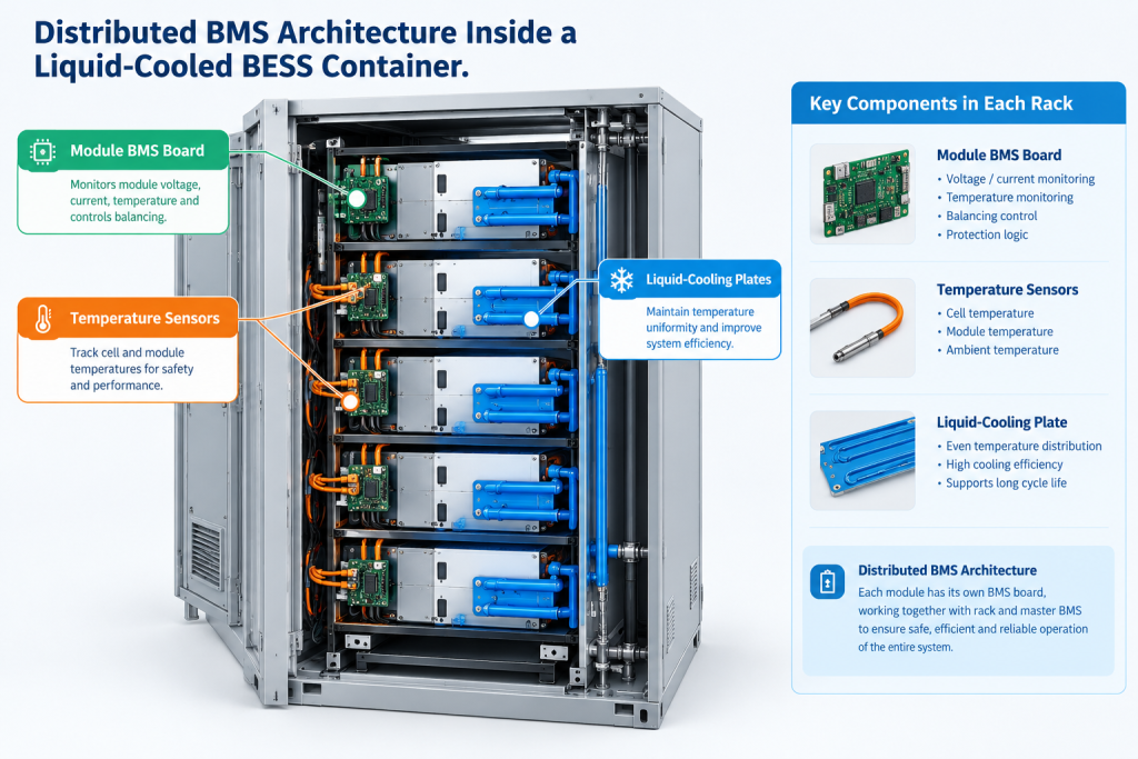
In a typical containerized BESS used in solar applications, the BMS is distributed across three tiers:
- Module-level (slave) boards measure individual cell voltages and temperatures.
- Rack-level BMS units aggregate data, perform balancing, and control local contactors.
- Container-level master BMS synthesizes the overall state of charge (SOC), state of health (SOH), and real-time charge/discharge limits for the entire string or container.
Key responsibilities include continuous voltage, current, and temperature monitoring; passive or active cell balancing; accurate SOC and SOH estimation; publication of dynamic power limits; and rapid isolation of faulty modules or racks.
The BMS does not decide whether the system should charge from excess solar generation or discharge into a peak. It simply declares what the battery can safely accept or deliver at any moment. Those limits are non-negotiable. If the EMS requests 2 MW of discharge but the BMS reports only 1.4 MW available because of temperature or SOC constraints, the higher systems must obey.
In liquid-cooled BESS containers—now the preferred choice for high-energy-density solar storage projects—the BMS works hand-in-hand with the thermal management system. Uniform cell temperatures improve both the accuracy of SOC estimates and the usable energy over the project lifetime.
Power Conversion System (PCS): The Bridge Between Battery and Grid
The PCS is the bidirectional power electronics interface that converts direct current from the battery into alternating current for the site or grid, and vice versa during charging.
In solar-plus-storage applications the PCS must do far more than simple conversion. It must:
- Synchronize with the grid or form a microgrid when needed
- Deliver precise active and reactive power
- Meet strict grid codes for voltage and frequency ride-through
- Respond in milliseconds to EMS setpoints while respecting BMS limits
- Maintain high efficiency across a wide operating range
Modern utility-scale and large C&I BESS designs increasingly favor string PCS architectures (multiple smaller units) over a single large central inverter. String designs improve partial-load efficiency and provide better redundancy—critical when the storage system is supporting a large solar array whose output varies throughout the day.
The PCS sits at the boundary between the DC container world and the AC plant world. Downstream it connects through medium-voltage transformers and switchgear to the point of interconnection. Upstream it receives power limits from the BMS and setpoints from the EMS or Power Plant Controller.
A high-quality PCS that is poorly integrated with the BMS will still underperform. Derating caused by temperature, voltage windows, or communication lag can quietly erode the revenue stack that justified the solar-plus-storage investment in the first place.
Hover over a data point to compare efficiency at each load level.
Energy Management System (EMS): The Strategic Brain of the Project
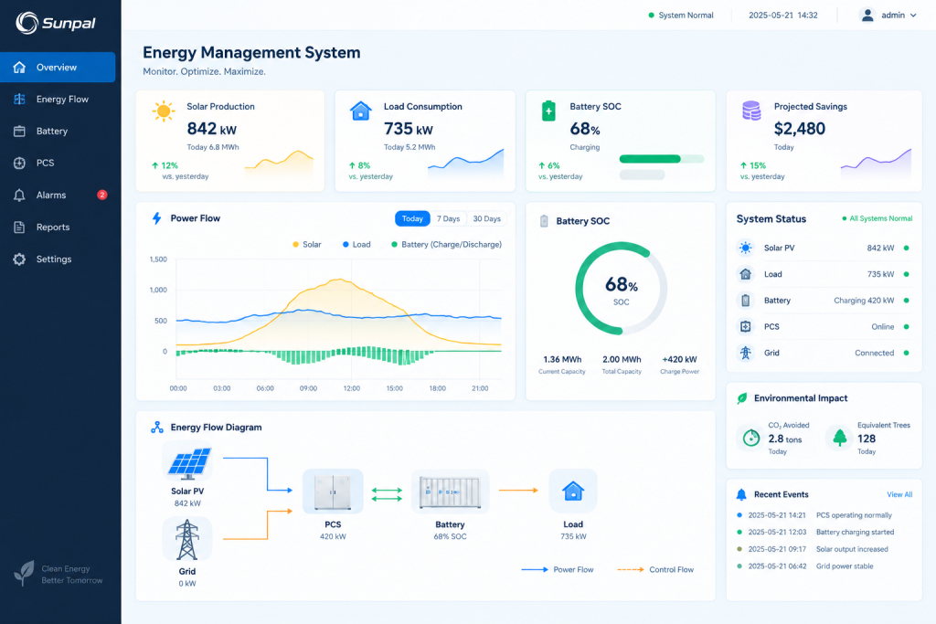
If the BMS protects the asset and the PCS moves the power, the EMS decides the strategy. It is the layer that turns a battery into a revenue-generating or cost-saving asset for the solar project owner.
Typical EMS inputs in a solar energy storage system include:
- Real-time site load and solar PV production
- Electricity tariffs or market prices
- Weather and solar irradiance forecasts
- Battery SOC and available power limits from the BMS
- Grid signals or utility dispatch commands
- Export limits and demand-charge thresholds
From these inputs the EMS calculates optimal charge and discharge schedules—peak shaving, energy arbitrage, renewable firming, frequency response, or backup reserve. It then issues setpoints to the PCS units while continuously monitoring that those setpoints remain inside the envelope published by the BMS.
In larger plants the EMS often works alongside a dedicated Power Plant Controller (for fast grid-code compliance) and a SCADA system (for monitoring, alarming, and historical data). The EMS itself focuses on economic and operational optimization on timescales of seconds to hours.
A sophisticated EMS can dramatically improve the internal rate of return of a solar-plus-storage project. A poorly configured one can leave valuable capacity stranded or cause the system to miss peak events.
How the Three Systems Actually Work Together in Real Time
Consider a typical commercial solar-plus-storage facility aiming to keep grid import below a demand threshold.
- The EMS detects rising site load and calculates that 800 kW of battery discharge is required for the next 15 minutes.
- It sends the 800 kW setpoint to the PCS units.
- Each PCS checks its own electrical limits and the latest power ceiling published by the BMS.
- The BMS, seeing slightly elevated temperatures in two racks, temporarily reduces the available discharge power to 720 kW and communicates the new limit.
- The PCS and EMS accept the reduced value. Actual power is delivered. Temperature and SOC data continue to flow upward so the EMS can update its forecasts.
This continuous hand-off—request, validation, execution, feedback—happens every few seconds. Supporting systems play critical supporting roles: liquid-cooling plates keep temperatures stable so the BMS does not have to derate aggressively; thermal propagation barriers and fire suppression provide last-line protection; DC busbars collect current efficiently; MV switchgear and transformers deliver clean power to the grid.
When any link in this chain is weak, the entire solar energy storage system suffers.
Side-by-Side Comparison: PCS vs BMS vs EMS at a Glance
| Aspect | BMS | PCS | EMS |
| Primary question | Is the battery safe? | Can power be converted & delivered? | When and why should power move? |
| Main focus | Cells, modules, racks | DC bus ↔ AC interface | Site, tariffs, solar production, grid |
| Typical timescale | Continuous to milliseconds | Milliseconds | Seconds to hours |
| Authority | Hard safety limits | Electrical execution within limits | Strategic setpoints |
| Key data handled | Voltage, current, temperature, SOC, SOH | Active/reactive power, voltage, frequency | Load, PV output, prices, forecasts, limits |
| Failure impact | Safety risk, accelerated degradation | Loss of power delivery | Sub-optimal revenue or cost savings |
This table is one of the most useful tools for solar project teams during procurement and commissioning.
Why System Integration and Container Design Matter More Than Ever
Buying the best individual components is not enough. In today’s market, leading solar and storage providers differentiate themselves through deep BESS system integration—especially inside the container.
Liquid-cooled thermal management has become a decisive factor. By maintaining tight temperature uniformity across thousands of cells, it allows the BMS to operate with higher accuracy and the PCS to avoid unnecessary derating. Fire suppression systems, thermal propagation barriers between racks, robust DC busbar design, and clean communication architecture between BMS, PCS, and EMS all contribute to higher availability and longer asset life.
For utility-scale solar storage and large commercial installations, the container is no longer just a weatherproof box. It is a carefully engineered subsystem that must arrive on site ready for rapid interconnection.
Practical Takeaways for Solar Developers, EPCs, and Asset Owners
When evaluating a BESS for a solar project, ask these questions:
- How are real-time limits from the BMS enforced by the PCS and respected by the EMS?
- What communication protocols and failover behaviors are implemented?
- How does the thermal management system (especially liquid cooling) support the BMS accuracy and PCS performance?
- Can the EMS optimize across solar production, time-of-use rates, demand charges, and any grid-service opportunities?
- What visibility does the SCADA system provide down to rack and module level?
The answers will tell you far more about long-term performance than a simple MWh or MW rating.
Closing Thoughts: From Components to Coordinated Performance
PCS, BMS, and EMS are not competing technologies. They are complementary layers in a sophisticated control hierarchy that turns stored solar energy into reliable, valuable electricity. When these three systems—and the supporting architecture around them—are designed and integrated as a coherent whole, the result is a BESS that delivers on its promises for decades.
Understanding the distinct roles of each system, and how they fit into the full Plant-to-Cell architecture, is one of the highest-leverage steps any solar professional can take toward safer, more profitable energy storage projects.