



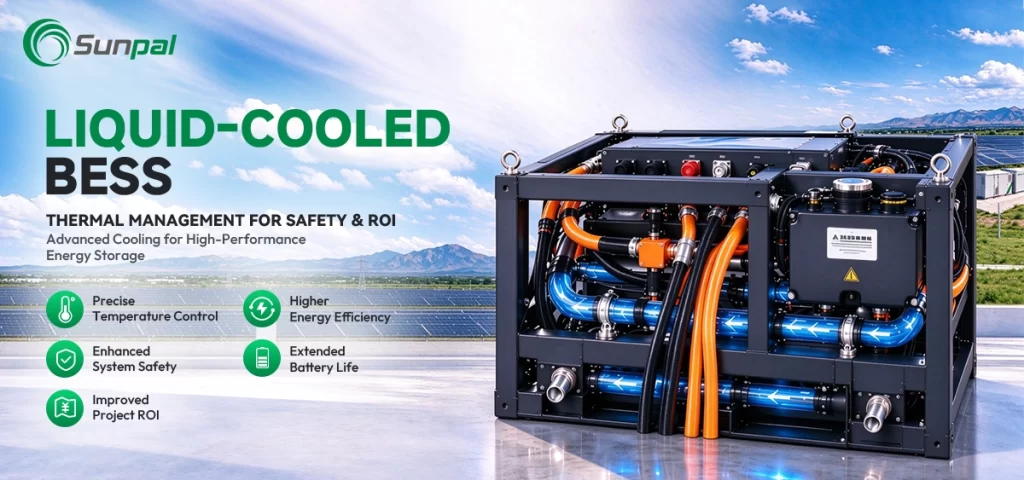
In the rapidly expanding world of solar-plus-storage projects, the conversation has shifted. Developers and asset owners no longer ask only how much energy a system can store. They ask how reliably it can deliver that energy over 20 years, under extreme temperatures, at high power rates, and without catastrophic risk. The answer increasingly points to one critical factor inside every utility-scale installation: thermal management of the BESS container.
Liquid-cooled battery energy storage system containers have moved from niche technology to the preferred architecture for modern grid-scale projects. When temperature control is precise, cell aging slows, thermal runaway risk drops dramatically, and project returns improve. When it is not, even the best cells and most sophisticated software cannot fully protect safety or ROI. This article walks through the complete BESS architecture—from plant level down to the individual cell—to show exactly why liquid cooling sits at the center of both safety and economic performance.
The New Reality of Solar Energy Storage: Why Temperature Rules Everything
Battery energy storage system components must work together as a coherent whole. A 100 MW / 400 MWh project may contain thousands of battery modules, dozens of power conversion systems, complex switchgear, and layers of control software. Yet the entire system lives or dies by the temperature of the cells inside each BESS container.
Industry data consistently shows that lithium-ion cells operate best in a narrow window, typically 15–35 °C, with temperature differences across a rack held below 5 °C. Outside that window, capacity fade accelerates, internal resistance rises, and the probability of thermal events increases. In hot climates common to many solar farms—Arizona, the Middle East, Australia, southern Europe—ambient temperatures routinely push air-cooled containers beyond safe operating limits during peak solar generation hours. Liquid cooling solves this constraint by removing heat directly at the source.
For solar companies and independent power producers, the implication is clear. Choosing the right thermal management approach is no longer a secondary engineering detail. It is a primary driver of system availability, warranty claims, insurance costs, and levelized cost of storage.
Mapping the Full BESS Architecture: Five Layers That Must Work as One
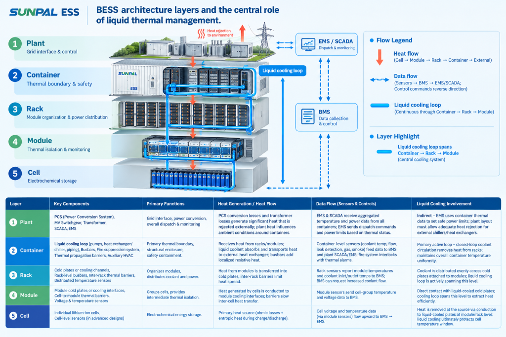
A complete BESS architecture can be understood as five nested layers: Plant → Container → Rack → Module → Cell. Each layer has distinct components, yet thermal behavior at the lowest level influences decisions at the highest.
At the plant level sit the power conversion system (PCS), medium-voltage switchgear, step-up transformers, SCADA, and energy management system (EMS). These elements determine how the storage asset interacts with the grid and with the solar array. Heat generated by the PCS and transformers must be managed, and the EMS must respect temperature-based power limits coming from the containers.
The BESS container itself is the primary thermal boundary. Inside it are the battery racks, liquid cooling loops, busbars, fire suppression systems, and thermal propagation barriers. This is where liquid cooling delivers its greatest value.
Moving inward, the rack organizes modules and distributes coolant. The module groups cells and incorporates local barriers and sensors. Finally, the cell is the electrochemical heart where heat is generated during charge and discharge.
Effective BESS system integration requires every layer to share temperature data and respond coherently. Liquid cooling provides the physical foundation that makes this coordination possible at high energy densities.
Plant-Level Integration: Setting the Stage for Thermal Performance
In a solar-plus-storage plant, the PCS converts DC battery power to AC for the grid or for hybrid operation with the PV array. Conversion losses appear as heat. In large installations, multiple megawatts of thermal load can originate from the PCS units alone. Medium-voltage switchgear and transformers add further heat that must be rejected to the ambient environment.
The EMS sits above these power components. It decides when to charge from excess solar generation, when to discharge into peak demand windows, and how aggressively to cycle the batteries. Modern EMS platforms receive real-time temperature telemetry from every container. If liquid cooling maintains tight temperature control, the EMS can dispatch more freely and capture higher revenue. If temperatures drift, the EMS must curtail power, reducing both capacity factor and revenue.
SCADA systems provide the operator visibility needed to detect cooling anomalies early. Together, these plant-level battery energy storage system components create the operational envelope within which the containers must perform. Sunpal Group's approach to BESS system integration emphasizes early coordination between plant electrical design and container thermal design so that neither constrains the other.
Inside the Liquid-Cooled BESS Container: The Thermal Heart of the System
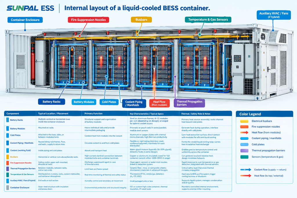
The BESS container is where thermal management becomes tangible. A typical liquid-cooled design places battery racks in a sealed or semi-sealed enclosure. Cold plates or cooling channels sit against the modules or cells. A closed-loop coolant—often a water-glycol mixture—circulates through these plates, absorbing heat and carrying it to a heat exchanger or chiller unit, frequently mounted on the container exterior or in a dedicated thermal management skid.
Compared with traditional air cooling, liquid systems achieve far tighter temperature uniformity. Air-cooled containers can exhibit 10–15 °C differences between the hottest and coolest cells under high load. Liquid-cooled designs routinely hold differences below 3–5 °C. That uniformity translates directly into more even aging, higher usable capacity, and lower risk of localized hotspots that can initiate thermal runaway.
Additional container-level components play supporting roles. Busbars must be sized and routed to minimize resistive heating. Fire suppression systems—often clean-agent or water-mist—are tightly integrated with temperature and gas sensors so that any abnormal rise triggers rapid response. Thermal propagation barriers between racks and modules slow or stop the spread of heat and flame if a single cell fails.
HVAC units may still appear in hybrid designs for humidity control or auxiliary cooling, but the primary heat load is handled by the liquid loop. This architecture allows higher packing density, quieter operation, and better performance in dusty or high-temperature solar farm environments.
From Rack to Cell: Where Heat Meets Electrochemistry
At the rack level, coolant is distributed evenly so every module receives comparable cooling. Sensors feed temperature data to the battery management system (BMS). The BMS continuously monitors cell voltages, temperatures, and currents. When it detects rising temperatures, it can request reduced power from the EMS or signal the cooling system to increase flow.
Modules incorporate their own thermal barriers—often ceramic or composite sheets—that limit heat transfer between adjacent cells. At the cell level, modern lithium-ion chemistries still generate heat through ohmic losses and entropy changes during high-rate cycling. Liquid cooling removes that heat before it accumulates.
The multi-layer barrier strategy—cell, module, rack, and container—combined with active liquid cooling creates defense-in-depth against thermal runaway. Industry analyses of utility-scale incidents show that systems with effective liquid cooling and robust barriers experience significantly lower propagation rates when a single cell fails.
Safety First: How Liquid Cooling Changes the Risk Profile
Safety remains the non-negotiable foundation of any energy storage project. Thermal runaway is the most feared failure mode. Once a cell reaches critical temperature, it can release flammable gases and heat that ignite neighboring cells. Liquid cooling addresses this risk in three ways.
First, it keeps the entire population of cells farther from the critical temperature threshold under normal and high-load conditions. Second, rapid heat removal can interrupt the early stages of a thermal event before it becomes irreversible. Third, the closed nature of many liquid-cooled containers limits oxygen availability and contains any vented gases for more effective suppression.
When these physical measures are paired with intelligent BMS algorithms and EMS interlocks, the probability of a container-level incident drops substantially. For solar asset owners, that reduction improves insurance terms, eases permitting, and protects the long-term bankability of the project.
BESS Thermal Performance
Temperature Rise & ΔT Comparison
Typical cell temperature rise and maximum-to-minimum cell temperature difference under sustained 1C charge/discharge.
Average Temperature Rise
20 → 7.5 °C
The illustrative midpoint is 12.5 °C lower with liquid cooling, equivalent to a 62.5% reduction in temperature rise.
Cell Temperature Difference (ΔT)
12 → 3.5 °C
The illustrative midpoint is 8.5 °C lower with liquid cooling, equivalent to approximately a 70.8% reduction in ΔT.
Typical temperature rise and cell-to-cell ΔT under 1C charge/discharge – Air-cooled vs. Liquid-cooled BESS containers (industry benchmark ranges).
Note: Bar heights use the midpoint of each supplied benchmark range. Values are approximate and depend on ambient temperature, cell chemistry, rack design, sensor placement, airflow, coolant flow, and operating conditions. Temperature rise is measured above ambient; ΔT is the maximum-to-minimum cell temperature difference. The comparison is illustrative, not a guarantee of performance for every BESS installation.
The ROI Equation: Turning Degrees into Dollars
Safety and economics are tightly linked. A container that runs 8–10 °C cooler on average can experience substantially lower calendar and cycle aging. Extended cycle life means the same battery investment delivers more lifetime throughput. Tighter temperature control also allows higher continuous power ratings without hitting thermal limits, increasing revenue from frequency regulation, peak shaving, or solar shifting.
Auxiliary power consumption is another lever. Well-designed liquid cooling systems can be more energy-efficient than large air-handling units under high heat loads, especially when free cooling or optimized chiller controls are used. Lower parasitic load improves the round-trip efficiency of the entire storage system.
Consider a conceptual 100 MW / 400 MWh solar-plus-storage project. If liquid cooling enables 5–8 % higher lifetime energy throughput and 1–2 % higher average availability while reducing cooling-related energy use, the impact on levelized cost of storage is material. Insurance premiums and potential downtime costs add further upside. These gains compound over a 20-year project life.
Sunpal Group's utility-scale BESS solutions are engineered with this full economic picture in mind, integrating container thermal design with PCS selection, BMS strategy, and EMS optimization from the earliest stages of system integration.
BESS Lifecycle & Thermal Management
Projected Capacity Retention over 10 Years
Illustrative lithium-ion cell capacity retention under different average operating temperatures. Lower temperature scenarios retain more capacity in this model.
25 °C at Year 10
82%
Projected remaining capacity in the lower-temperature scenario.
35 °C at Year 10
64%
Projected remaining capacity in the higher-temperature scenario.
Illustrative 100 MWh BESS
+18 MWh
An 18-percentage-point retention difference corresponds to approximately 18 MWh of capacity on a 100 MWh reference basis.
Why temperature management matters over a 10-year project life
In this illustrative model, maintaining cells closer to 25–30 °C is associated with higher projected capacity retention than operating at 35–40 °C. Better retention may help reduce augmentation requirements, preserve energy throughput and support lower lifetime storage costs. Actual financial value depends on usable-energy limits, operating strategy, degradation, market revenues, financing and augmentation costs.
Projected capacity retention over 10 years for lithium-ion cells held at different average temperatures (industry model benchmarks).
Note: These are approximate illustrative model values, not a universal degradation guarantee or a validated forecast for a specific battery. Actual retention depends on cell chemistry, cycle depth, charging rate, time at high state of charge, calendar aging, thermal history and warranty conditions. The 18 MWh comparison assumes the percentage-point difference applies directly to a 100 MWh reference capacity; it does not by itself establish 18 MWh of additional deliverable energy or a specific financial return.
Practical Best Practices for Liquid-Cooled BESS System Integration
Successful projects follow a consistent set of principles. Thermal design must begin at the cell and module level and propagate upward. Coolant chemistry, flow rates, and cold-plate contact quality should be validated under realistic duty cycles. Redundancy in pumps and sensors protects against single points of failure.
Control integration is equally important. The BMS, cooling system controller, and plant EMS must share a common data model so that temperature limits automatically influence dispatch decisions. Commissioning should include thermal mapping under load to verify that design ΔT targets are achieved across every rack.
Common pitfalls include undersized heat rejection capacity for peak solar-hour conditions, inadequate leak detection, poor barrier installation, and late-stage electrical interface mismatches between containers and plant PCS. Addressing these issues early in the design phase is far less costly than retrofitting in the field.
Looking Ahead: Liquid Cooling as the Standard for High-Performance Solar Storage
As solar energy storage projects grow larger and energy densities continue to rise, air cooling is reaching its practical limits in many climates and use cases. Liquid-cooled BESS containers offer a proven path to higher safety margins, longer asset life, and stronger project returns. When the full BESS architecture—from plant PCS and EMS down to the individual cell—is designed around precise thermal control, the storage system becomes a reliable partner to the solar array rather than a source of operational risk.
The five-layer framework makes the interdependencies clear. Thermal management is not an isolated container feature; it is the thread that runs through every battery energy storage system component. Developers, EPCs, and asset owners who treat it as a core design priority will field systems that perform safely and profitably for decades.
For teams evaluating their next utility-scale or commercial solar-plus-storage project, the question is no longer whether liquid cooling belongs in the architecture. The question is how thoroughly it is integrated across every layer of the BESS. Ready to design a safer, higher-ROI storage system? Explore Sunpal Group's complete BESS architecture resources, review our liquid-cooled container solutions, and connect with our system integration experts today to discuss your project requirements and receive a customized technical proposal.